Device Assembly
Brew Bubbles runs on an ESP8266 controller. To detect the information to be logged, you need to connect specific devices to the controller. I have provided a circuit board design, sometimes called a “shield,” to make this easier.
Assembly is not difficult, but it does require some basic soldering.
Contents
Materials Required
This shield uses one or two each of some widely-available and inexpensive components. You may find you are better off buying a resistor assortment, for instance. Buying 10 or 20 of a piece at a time for a nominal cost from China is also possible. Make several!
Gather the following parts and pieces:
Controller
The ESP8266 controller is paired with many different “developer boards” to make connections easier. Do yourself a favor and do not buy a bare ESP8266 chip. I can’t help you if you do.
The developer board used in this project is the Wemos D1 Mini. Wherever you purchase it, make sure it is an ESP-12F (if that information is listed) and that it says 4MB (or sometimes shown as 32Mb, which is 4 megaBYTES converted to megaBITS.) Also, be sure it comes with the 8-pin male and female headers, or else you will need to get them elsewhere. You can find the Wemos D1 Mini in many places; here are a few:
- The “Legitimate” Way: The Chinese have knocked the Wemos D1 Mini has mercilessly. This situation is ironic since Espressif makes the ESP8266 controller, and they are a Chinese company. In the past, wemos.cc was the way to buy the “original” Wemos D1 Mini. However, they no longer appear to sell directly, and instead, the website is a wiki-type information source.
- The Quick Way: Why Amazon, of course. You can search for “Wemos D1 Mini” (it has to be “mini” and not “pro”) and find a large number of different ways to buy. My preference is to get a handful at a time since they are cheaper that way. This link gives you five for $17.99 in a couple of days with free Prime shipping ($3.60/ea.)
- The Cheap Way: AliExpress has everything anyone would ever need, so long as that person can wait a month or more for delivery. For $1.99 each, this way is as cheap as it gets. Be aware that there are different sellers on there, and each ship independently. Sometimes you save by paying less on shipping if you are buying multiple things from one seller.
Printed Circuit Board
The pcb directory in the repository contains the Eagle files for the printed circuit board shield supporting Brew Bubbles. The shield provides the necessary component connections and circuitry for the ESP8266 controller used in this project. It is nearly identical in size to the Wemos D1 mini we use, providing a very compact and lightweight footprint. A sub-directory also contains Gerber files for people who need those.
Everyone likes to save a dollar, including me. There used to be other recommendations for PCB manufacturers, but quality, responsiveness, and dependability have forced me to limit my recommendations to OSH Park. You can buy three boards for $5.70 (plus shipping) at this link.
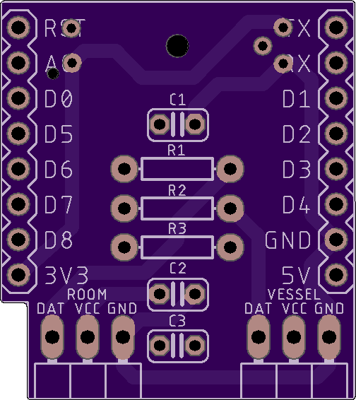
Displayed below is a view of the top of the printed circuit board, as rendered by OSH Park.
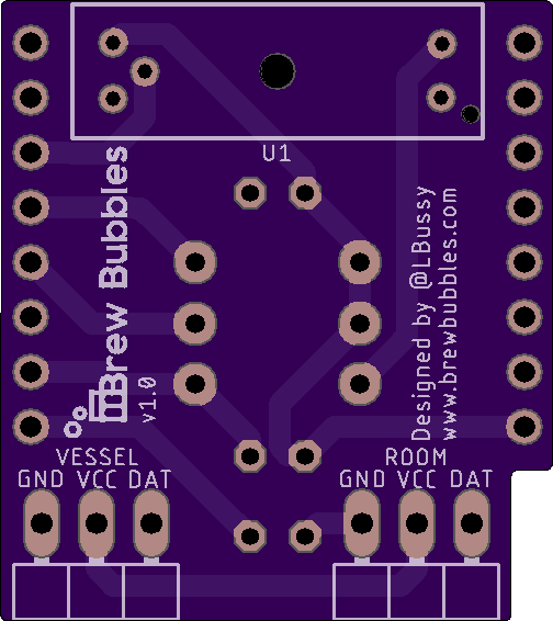
Below is a view of the bottom of the printed circuit board, as rendered by OSH Park.
If you would like to personalize these board designs, you may modify them with Autodesk’s EAGLE. EAGLE is a scriptable electronic design automation (EDA) application with schematic capture, printed circuit board (PCB) layout, auto-router, and computer-aided manufacturing (CAM) features. EAGLE stands for Easily Applicable Graphical Layout Editor and is developed by CadSoft Computer GmbH.
General Parts
These are the parts which you can get pretty much anywhere.
The items marked with an *asterisk below are optional. They are in the design to provide a means to monitor and trend the ambient temperature where you place the fermenter and the fermenting liquid’s temperature via a thermowell or insulated in contact with the fermenter. If you choose not to use these, the firmware automatically skips reporting these readings.
| Quan | Description | Placement |
|---|---|---|
| 3 | 0.1uF 10V Ceramic Capacitor | C1, C2, C3 |
| 2* | 2.2k ohm 1/4W 5% Axial resistor | R1, R2 |
| 1 | 150 ohm 1/4W 5% Axial resistor | R3 |
| 2* | 3-Pin 90-degree Header | VESSEL, ROOM |
| 1 | GP1A57HR Transmissive Photointerrupter | U1 |
| 2* | DS18B20 Temperature sensor and lead | VESSEL, ROOM |
This BOM is available on Mouser. You can find these parts in just about any of the usual places. Please make sure they are the proper rating and form factor.
If you choose to use the temperature sensors, you need to obtain two (2) Waterproof DS18B20 Temperature Sensor with leads. These are the same as used with the various fermenter temperature control projects such as BrewPi Remix. You also need to crimp on a three-terminal female plug. You can get a kit on Amazon with more terminals than you ever need, including the crimping tool, for about $25 or save by doing some careful AliExpress shopping.
Component Installation
You are going to have to solder. If you have legitimately never soldered anything before, I recommend you spend a few minutes on YouTube and watch a few videos. Sparkfun also has a very nice tutorial. It is not hard at all once you get the hang of it. While the shield is comparatively small, the components chosen are simple through-hole parts, which may be easily soldered by a beginner with a little patience.
I do not intend to provide a step-by-step on how to solder here. Still, I recommend the following part installation order for ease of assembly:
- Resistors - As the shortest mounted components, soldering the three resistors to the board first is the least challenging. They are also some of the most tolerant parts, so these grant you some experience to get you going.
- 3-Pin headers - These components are not sensitive to the heat except for the plastic.
- Capacitors - These are mounted next. Be sure to get them as close to the board as possible since having them stick up changes their intended impact on the circuit.
- 8-pin female headers - These are the tallest items on the front side of the board and are the last pieces to go on this side. Lightly tack on one pin and make sure the header is straight. When you have it positioned correctly, start from the other end, and solder the pins correctly. If you have a D1 laying around with the pin headers soldered on it already, using that to steady the parts helps. This process is a chicken or the egg choice with the next item. The first part to be soldered, either the controller or shield is the most difficult. After that, you can use the other to steady the headers of the first. If you have a breadboard, you may also employ that to steady the parts.
- 8-pin male headers - These need to be soldered on the controller board. See note on #4 above.
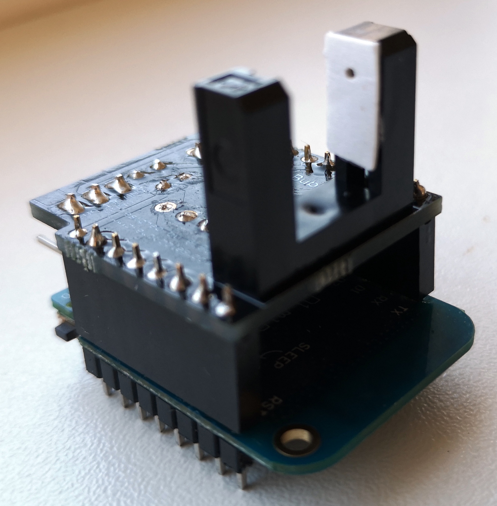
- GP1A57HR photo-interrupter - If the controller is still attached, take it off temporarily. The photo-interrupter goes on the back side of the circuit board in the outline provided. Therefore you solder it from the top side. If you put it on the wrong side, you can remove the solder (more YouTube work), but I’m not going to lie: it is frustrating. Be careful to do it right the first time.
Once you have finished soldering the shield, make sure to clean off the flux. You can use cheap vodka or Everclear, or a commercially available flux solvent.
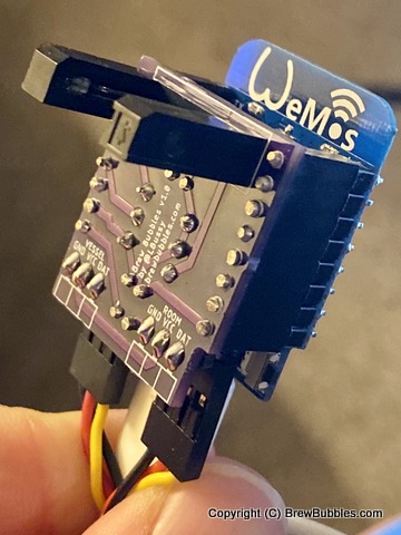
It should be apparent by now that the Wemos should plug into the shield. There is a notch in the shield, which corresponds to the notch in the Wemos. The controller should be on the same side as the components as shown:
Sensors
Obtain some Dupont headers and a crimper from any of the usual places. Crimp a 3-pin female header on your sensors and plug them in. Some have asked about the pin order and the potential to change it to facilitate soldering a DS18B20 sensor directly to the PCB. That configuration was how I did my early prototypes, and it was a nicer form factor. However, I quickly found out that the ESP8266 would heat the surrounding parts, and the sensor read about 10°F higher than it should. Other projects get away with this, I believe, because they use sleep mode on the controller. As a web-delivered application, that was not an option for me.
Light Filter
These widely-used sensors are everywhere. Using them for this application sometimes takes a little tweaking to make it perfect. When developing Brew Bubbles, I got lucky and ended up with a couple of sensors that worked perfectly out of the box. After release, I discovered that most people were not so fortunate. Because the airlocks and water are clear, these other sensors failed to register bubbles correctly.
The Sharp GP1A57HRJ00Fit emits 950 nm light, and the receptor is sensitive to 400 through 1200 nm. That ranges from blue/violet through infrared. The sensor is most sensitive to IR light (700 nm – 1 mm) at 900 nm. Water absorbs infrared far better than the lower visible wavelengths:
IR filters are standard in photography but possibly expensive to purchase. Unless you have one you can cannibalize, this approach might be pricey. What’s not pricey are gels used for lighting in photography, stage, and film making. There are infrared gels, but these too are expensive and more difficult to find. What we used to do in the Army to make a flashlight for night-vision devices was to take our angle-head flashlights and put on the red and green filters. Red blocks all but red and green blocks all but green. The combination blocks pretty much all visible light but allows IR to pass.
I tested this with gels I purchased online, which did not turn out to be as effective as I thought. I could also see through the gels when I looked around the room, so I suspect they were not optimal for this purpose. If you have an IR filter available, that might be a good thing to try. Otherwise, users @ChrisThomas and @wd16261 on Homebrewtalk came up with a very practical solution:
Here, ChrisThomas uses double-stick tape and a small piece of cardboard with a pinhole:
And here, wd16261 uses a piece of shrink-tubing with a dot of glue to hold his pinhole camera in place:
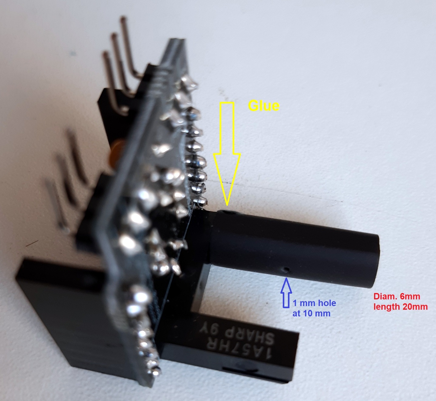
Both of these form collimators that restrict the amount of light entering the sensor. Both seem to be very effective and likely simpler than messing with light filters.
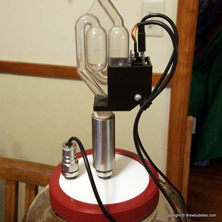
Bracket and Mounting
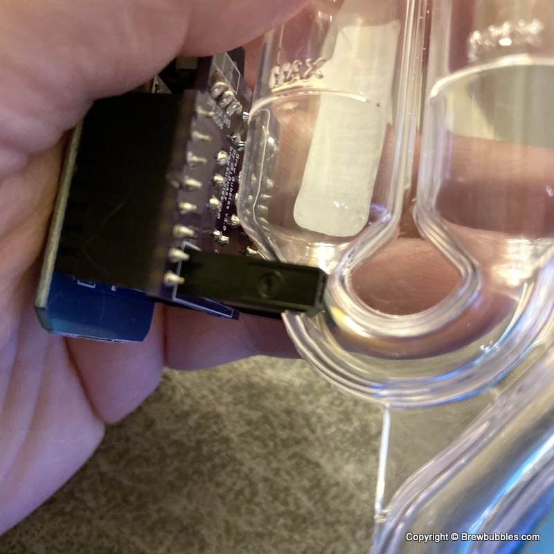
Position the photo-receptor such that the U-gap surrounds the bottom of a fermentation S-Lock. In this way, when bubbles pass by, they are registered and counted.
You should certainly feel free to use duct tape or a rubber-band or whatever suits you to affix Brew Bubbles to the airlock. I have included a 3-D printable bracket design in the project for those who desire a more finished approach. The completed controller & shield combo is slid into the top to allow the temperature sensor connectors to point up. The airlock is then passed through the hole in the bracket and into the carboy stopper. The hole may need to be adjusted larger or drilled out depending on the size of your airlock. If it is too loose around the airlock, a drill stop or even tape may be used on the tube under the bracket to hold it in place.
There is a hole in the bracket side intended to allow using a pop-rivet or small screw to secure the temperature sensor cable(s) with an R-type cable clamp. I recommend this to avoid strain on the small wires.